
Labyrent Game With Pinoo
Purpose of the Project: To create a maze game with the servo motor module and joystick module using the Pinoo control card.
Duration: 2 lessons
Age Group: 7 years and older
Pinoo Set: Full and Maker Set.
Benefits:
• Learns to code Pinoo control card
• Learns to code the joystick module.
• Learns to code the servo motor module.
• Improves the skill of setting up algorithms.
• Improves coding skill.
• Designs and plays his own game.
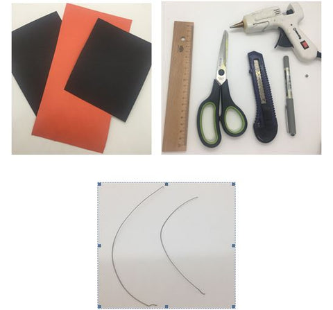
Materials to be Used: Mblock 3 program, Pinoo control card, joystick module, 2 servo motor modules, connection cable

Materials Required for Design: Colored cardboard, ruler, pencil, knife, scissors, silicon gun and silicone, ball, aluminum wire.
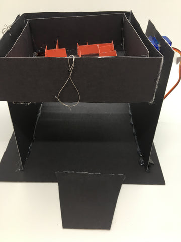
Project Preparation:
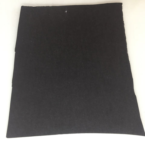
1. For the base of the labyrinth, we cut a 20 cm square from the cardboard with the help of scissors.

2. For the edges of the labyrinth, we cut 2 trapezoidal 14 cm by 16 cm isosceles.

3. We drill a rectangular hole in the middle of one of the isosceles trapezoids so that the servo motor can fit.
NOTE: This servo motor will move on the X axis, ie right and left directions.

4. We drill a small hole in the other part, in the middle of the rectangle we cut for the servo motor.
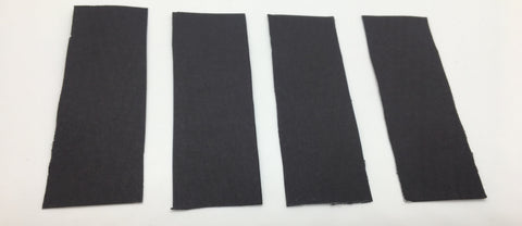
5. For the support inside the labyrinth, we cut 4 rectangles of 14 cm by 4 cm.

6. We create a square by sticking rectangles end to end with the help of a silicone gun.

7. We drill a rectangular hole in the middle of one side of the square that we have created, with the help of the curved knife to fit the servo motor.
NOTE: This servo motor will move on the Y axis ie up and down directions.

8. In the middle of the outer part of the edge to the left of the hole, we mount the servo motor propeller horizontally with the help of a silicone gun.

9. We drill a small hole in the middle of the rim to the right of the rectangular hole.

10. We connect the hole we drilled in the trapezoidal part and the hole we drilled in the square by means of aluminum wire so that it is not too tight.

11. We mount our motor with the help of a silicon gun to the hole we drilled in the isosceles part for the servo motor.

12. We connect the propeller we attached to the square and the servo motor.
NOTE: We will separate the propeller and the motor in the coding part. Therefore, do not stick them together!

13. We mount the joined edges on the labyrinth floor with the help of a silicone gun.

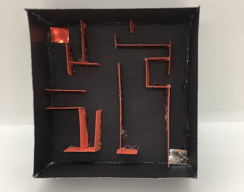
14. For the labyrinth, we cut a 12cm x 12cm square from the cardboard.

15. For the walls of the labyrinth, we cut 4 rectangles of 12cm by 4cm. Then we mount it on the sides of the square with the help of a silicone gun.
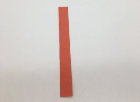
16. To design our labyrinth, we cut pieces of 1.5cm width from different colored cardboard.
NOTE: How much to cut will depend on the maze you want to make.
17. We design our labyrinth as we want. We attach cardboard to those parts in a way to show the starting and ending points.
18. We mount the motor to the rectangular hole we opened for the Y axis Servo motor.

19. We drill a small hole in the middle of the edge opposite the servo motor.

20. We drill a small hole in the middle of one side of the maze we have created.

21. We mount the propeller with a silicon gun in the middle part of the edge opposite the hole we drilled, corresponding to the servo motor.

22. We connect the hole we drilled into the labyrinth and the hole we drilled on the support part with the help of aluminum wire so that it is not too tight.

23. We combine the servo motor and propeller.
NOTE: We will separate the propeller and the motor in the coding part. Therefore, do not stick them together!

24. We cut 11cm by 8cm trapezoid in order to be able to put it under the joystick module.

25. We stick to the front of the game with the help of a silicone gun.
26. We mount the joystick module on our trapezoidal part with the help of a silicone gun.

27. We connect the servo motors with the servo motor modules in a way that corresponds to Brown cable-GND, Red cable-5V, Orange cable-D0.

28. We make our connections. We connect the joystick module to the red / yellow input number 9 with a connection cable. We connect the X-axis servo motor to the purple input number 3 with the help of a connection cable. We connect the Y-axis servo motor to the purple input number 2 with the help of a connection cable.
NOTE: Let's separate the servo motor and propellers.

29. We have completed our connections, now we go to the coding part. We will use mblock-3 application for this.
30. We connect our Pinoo control card to the computer with the help of a connection cable and enter the Mblock3 application.
Then we introduce our Pinoo control card to the computer.
For this, we first click on the serial port option from the Connect tab.
Then we choose COM3. (The number may differ depending on the computer and the port.)

31. After making the serial port connection, we select the card to be used from the Cards tab. We are working with the nano model of the Arduino

32. In order to add the Pinoo extension to our computer, we click on the Manage extensions option from the Extensions tab.
In the window that opens, we type "Pinoo" into the search engine and simply say download to the result. It was installed on our computer.


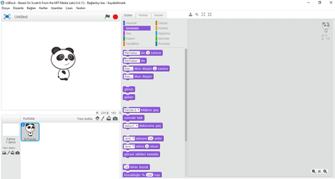
33. We come to the Extensions tab again and click on the Pinoo option. We will write our codes with the Pinoo extension.

34. In the coding part; To start the application, we get the code when the Green Flag is clicked from the Events menu.

35. Joystick module has two axes, x and y axis. We need to define variables to see their values.
For this reason, we click ‘’Create’’ a variable command in the
Data & Block menu.

36. On the screen that appears, we define separate variables as X axis and Y axis.


37. We get the continuous repeat command from the control menu. Then we take the codes from the Data & Block section to let the x axis be 0 and the y axis to be 0 and put them into the continuous repeat block.
.

38. We take the slash sign from the operations menu and place it above the number 0.
Our purpose to do this is to convert the value of the joystick module to the value of the servo motor.

39. We get the joystick code from the ‘’Robots’’ menu and set the x, y axes.

40. Then we write 5.683 to the right of the division operation. This is because; The joystick module takes values between 0-1023, while the servo motor module takes values between 0-180. When the value of the joystick module is at the top, that is, 1023, the servo motor module must also be at its highest value. We need to divide 1023/180 to equalize the incoming values and the result is 5,683

41. Now we click on the green flag and never touch the joystick module.
The servo motor modules will move according to the position of the joystick module in the middle. Then we click the red button and stop it. Next, let's reassemble the servo motor modules and propellers.
42. We get the servo motor codes from the Robots tab and do not forget to change the pin parts. Then we adjust their angles according to the axes of the joystick module.
We have attached the x-axis to the 3rd gate, so we equalize the x-axis from the data & block menu, and the 2nd gate to the y-axis.
Now, wherever we pull the joystick module, our servo motor module will move accordingly.

43. If there is no problem in the operation of our project, we need to load the codes we have written into our card in order to run our project with a power source independent of the computer.
For this, we throw away the "Click on the green flag" code we used at the beginning and the code that we made the puppet tell the sensor value and get the Pinoo Program code from the Robots menu.

44. Right click on the code and click the ‘’Upload to Arduino’’ option. (We work with arduino as a card.)

45. In the window that opens, we click the ‘’Upload to Arduino’’ button again.

46. We are waiting while our codes are being loaded to the card. After saying the installation is finished, we click on the close button.

47. If there is no problem, we disconnect our power cable from the computer. We power our Pinoo Control board with the help of a 9v battery and a battery cap. We also turn the on / off button right next to the battery input to the on position.
The Working Status of the Project:
When we don't move the joystick module, the maze game stays straight.

When we move the joystick module, it will move in that direction in the maze.
