
Smart Ladder with Pinoo
Purpose of the Project: To create a smart ladder system with light sensor (ldr) and leds using the Pinoo Control Card.
Duration: 2 lessons
Age Group: 9 years and older
Pinoo Set: Basic set, Invention set, Maker set ve Full set
Benefits:
- Learns to code Pinoo control board.
- Learns to code the light sensor (ldr).
- Led module learns to code.
- Algorithm building skill develops.
- Coding skill improves.
Materials to be Used:
Mblock 3 program, Pinoo Control Card, 2 pieces of Light sensor (Ldr), 2 pieces of LED module, RJ-11 Cables

Materials Required for Design: 12 small wooden pieces, 2 tongue sticks, paint, colored cardboard, silicone gun


Project Preparation:
1. We glue the two boards with an L-shaped silicone gun. We will do this step twice. Our aim is to get a ladder shape here.


- We build a support around it so that it can stand in balance.


- We will create an elevation in the lower part of the ladder in order to place the cables more properly. We will use the tongue bars here. We divide both the tongue bars in the middle. We attach them to the lower part of the ladder.

- We paint the ladder.

- We fix the light sensors (Ldr) to the steps.

- We fix the LEDs on the step walls.

-
For our leds, we connect the one on the first wall to the purple entrance number 1 and the one on the second wall to the purple entrance number 2.
We connect the light sensors to the red input number 7 in the first digit and the red input number 8 in the second digit.

- We have completed our connections, now let's move on to the coding part. For this we will use the Mblock-3 application.

-
Let's connect our Pinoo control card to the computer with the help of a connection cable and enter the Mblock3 application. Then, let's introduce our Pinoo Control Card to the computer. To do this, we first click on the serial port option from the Connect tab. Then we select COM3. (The number may differ depending on the computer and the port.)

- After making the serial port connection, let's select the card we will use from the cards tab. We are working with arduino nano model.

-
In order to add the Pinoo extension to our computer, we click on the manage extensions option from the extensions tab. In the window that opens, we type "Pinoo" in the search engine and click download to the result. It has been installed on our computer.


- We come to the extensions tab again and click on the Pinoo option. We will write our codes with the Pinoo extension.

-
In the coding part; To start the application, we get the code when the Green Flag is clicked from the Events menu.

-
We create two variables named sensor1 and sensor2 from the data & block tab to learn the value read by two sensors at the same time.

-
To define that the variables are equal to the light sensors, we take the code block from the data & block tab to get sensor1 0. From the Robots tab, we take the code block for the Pinoo Light Sensor. We do this for both variables and place it in the continuous repeat block from the control tab to make a continuous reading process.

-
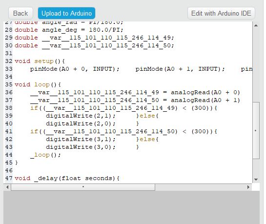
When we click on the green flag, let's move our hand closer to the light sensor and observe the value change of the variables. We have determined a threshold value of 300 as the threshold value for the dark value.

-
In the If section, we take the code block related to the led from the ‘’robots’’ tab and set the Pinoo1 input to high. If it is not for the part, that is, if the value is greater than 300, we bring the led status to low. Thus, the led will turn off.

- We do the same for the previous operation for the led in sensor2 and Pinoo2 input.

- After completing our codes, we check the operation of our project by clicking the green flag. When we covered the light sensor with our hands, that is, when someone pressed the step, our puppet showed a value less than 300 and our led on the step turned on.

-
If there is no problem in the operation of our project, we need to load the codes we have written into our card in order to run our project with a power source independent of the computer.

- Right click on the code and click on ‘’Upload to Arduino’’ (We work with Arduino as a board.)

- We are waiting for the codes to be uploaded to the card. After the installation is complete, we close the window.
- If there is no problem, we unplug our power cable from the computer. We power our Pinoo Control board with the help of a 9v battery and a battery cap. We also turn the on / off button right next to the battery input to the on position.