
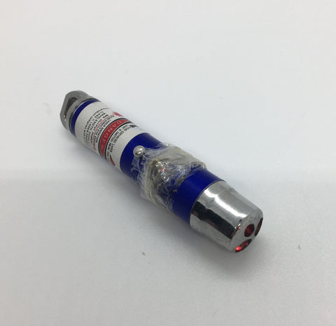
Laser Thief Alarm With Pinoo Ldr
Purpose of the Project: To create a laser burglar alarm project with led module, buzzer module and ldr light detecting sensor using the Pinoo control card.
Duration: 2 lessons
Age Group: 9 years and older
Set Used: Pinoo Basic Set
Benefits:
• Learns to code Pinoo control card.
• Learns to code the light detecting sensor.
• Learns to code the buzzer module.
• Learns to code the LED module.
• Improves the skill of setting up algorithms.
• Improves coding skill.
• Design skill develops.
Materials to be Used: Mblock 3 program, Pinoo control card, light detecting sensor, red led module, buzzer module, connection cables

Materials Required for Design: Decota, mirrored cardboard, eva, tape, silicone gun and silicone, pen, laser light, scissors, curved knife, ruler

Project Preparation:

First of all, we will create a box. To create the side walls of the box, we draw two 15x10cm rectangles on the decorate using a ruler and pencil. We cut rectangles with the help of a knife.

For the upper and lower parts of the box, using a ruler and pencil, draw two 15x12cm rectangles on the deco. We cut rectangles with the help of a knife.

For the back wall of the box, we draw a 15x15cm square on the decorate using a ruler and pencil and cut it with the help of a curved knife.

 We create a box by combining the pieces we cut with the help of a silicon gun.
Note: We leave a space in the front of the box to be able to place the laser light.

Let's cut three circles from mirror cardboard.

We stick a tape to the button so that the red light of the laser is constantly on. Then we mount it on the edge of the box with the help of a silicon gun so that the laser light reflects on the wall.

On top of the red light reflected on the wall, we glue the circular mirror cardboard we cut with the help of a silicone gun.


With the help of a silicone gun, we glue another mirrored cardboard onto the red light reflected on the other wall from the mirrored cardboard.


With the help of a silicone gun, we glue another mirrored cardboard onto the light reflected from the mirrored cardboard to the other wall.


We will assemble the light sensing sensor to match the light reflected on the opposite wall from the mirror cardboard. For this, we make holes with the help of a knife so that the socket part of the light detection sensor passes.


We mount the light sensing sensor to the hole drilled with the help of a silicone gun.

We mount the buzzer module on the side wall of the box with the help of a silicon gun.

We mount the red led module on the front of the box with the help of a silicon gun.

We decorate the box as we wish.
We connect the modules and the sensor to the Pinoo control card with the help of a connection cable. We connect the buzzer module to the purple input number 3.We connect the red led module to the purple input number 2.We connect the light sensing sensor to the red input number 7.

We have completed the connections and the design, now we go to the coding part. We will use mblock-3 application for this.

We connect our Pinoo Control Card to the computer with the help of a connection cable and enter the Mblock3 application. Then we introduce our Pinoo Control Card to the computer. For this, we first click on the serial port option from the Connect tab. Then we choose COM3. (The number may differ depending on the computer and the port.)

After making the serial port connection, we select the card we will use from the Cards tab. We are working with Arduino Nano model.

 In order to add Pinoo extension to our computer, we click on ‘’manage extensions’’ option from Extensions tab. In the window that opens, we type "Pinoo" into the search engine and simply say download to the result. It was installed on our computer.

We come to the Extensions tab again and click on the Pinoo option. We will write our codes with the Pinoo extension.
 Come to the ‘’Connect Again’’ tab and click on the ‘’Firmware Update’’ option. After saying that the installation is finished, we press the ‘Close’ button.
 In the coding part; To start the application, we get the code when clicking the ‘Green Flag’ from the ‘Events’ menu.

We get help from the dummy to learn the value read by the light detecting sensor. For this, we get the "say hello" command from the view tab. Instead of the word Hello, we get the code block for the light sensing sensor from the Robots tab. We change the pin input to Pinoo7 that we connect.


We click on the ‘green flag’ and look at the value measured by the light detector sensor in the light. (We assume that it measured values in about 900 s.) Then we put our hand into the box and look at the value measured by the light sensing sensor. (We assume that it measured value in about 200 s.)
 In order to check whether the buzzer module works or not, when the spacebar is pressed, we say play the G7 note. We change the pin input to Pinoo3 that we connect.

To check whether the LED module works or not, when the space key is pressed, we say LED high and turn on the LED. We change the pin input to Pinoo2 that we connect. When the up arrow key is pressed, we say low and turn off the led.

If the box is put in hand, that is, if the value measured by the light sensing sensor is less than 400, the red LED module will light up and the buzzer module will beep. If the value measured by the light detecting sensor is greater than 400, the buzzer and led module will stop passively.
 We click on the ‘green flag’ and try the project. If there is no problem in the operation of our project, we need to load the codes we have written into our card in order to run our project with a power source independent of the computer.
For this, we throw away the "Click on the green flag" code we used at the beginning and the code that we made the puppet tell the sensor value and get the Pinoo Program code from the Robots menu.

Right click on the code and click the ‘Upload to Arduino’ option. (We work with arduino as a card.)

In the window that opens, we click the ‘Upload to Arduino’ button again.

We are waiting while our codes are being loaded to the card. After saying the installation is finished, we click on the close button.
If there is no problem, we disconnect our power cable from the computer. We power our Pinoo control board with the help of a 9v battery and a battery cap. We also turn the ON / OFF button right next to the battery input to the on position.
Working Status of the Project:

When our light sensing sensor measures a value greater than 400, that is, when our valuables are not touched, the led and buzzer modules are passive.

When our light sensing sensor measures a value less than 400, that is, when our valuables are touched, led and buzzer modules are active.
Our Arduino IDE commands:
#define led 3 // 3.Pinde LED modülü olduğunu tanımlıyoruz
#define buzzer 4 // 4.Pinde BUZZER modülü olduğunu tanımlıyoruz

void setup() {
pinMode (led, OUTPUT); //LED modülünün çıkış elemanı olduğunu belirtiyoruz
pinMode (buzzer, OUTPUT); //BUZZER modülünün çıkış elemanı olduğunu belirtiyoruz
Serial.begin(9600); //9600 Baundluk bir seri haberleşme başlatıyoruz

}
void loop() {
int isik=analogRead(A0); //Işık değişkenini A0 pinindeki LDR ile okuyoruz
Serial.println(isik); //Okunan değeri seri iletişim ekranına yansıtıyoruz
delay(50);

if (isik<400){  //Okunan ışık değeri 400'den küçük ise
  digitalWrite(led,HIGH); //LED modülü yansın
  digitalWrite(buzzer,HIGH); //BUZZER modülü ses çıkarsın
}
else{
  digitalWrite(led,LOW); //LED yanmasın
  digitalWrite(buzzer,LOW); //BUZZER modülü sussun
}
}